This webpage gives a short introduction to the basic principles of light microscopy.
Brightfield Microscopy | Brightfield Koehler setup checklist
The most important feature of a microscope is its resolution,
the ability to see fine details. Once you can resolve fine details then you
can magnify them.
Every optical system has a finite resolution, if you magnify objects beyond the
resolution the result will be empty magnification. So, the actual
purpose of a microscope is to see small things clearly.
A second, desirable attribute of a microscope is depth of field, which is the range of depth that a specimen is in acceptable focus. A microscope that has a thin depth of field will have to be continuously focused up and down to view a thick specimen.
A third feature that a microscope has its mechanism for
contrast formation. In order to distinguish a feature from its
surrounding background the human eye needs a difference of 2 percent in intensity.
Contrast is the ratio between the dark and the light. Typically, most microscopes
use absorption contrast, that is the
specimen is subjected to stains in order to be seen. This is called
bright field microscopy.
There are other types of microscope that use more exotic means to generate
contrast, such as phase contrast, dark field, differential interference contrast.
The fourth desirable feature is a strong illumination source. The higher a microscope magnifies the more light will be required. Also, there will be more optical trade off leeway when there is more light present. The illumination source should also be at a wavelength (color) that will facilitate the interaction with the specimen. All microscopes fall into either of two categories based on how the specimen is illuminated. In the typical compound microscope the light passes through the specimen and is collected by the image forming optics. This is called diascopic illumination. Dissecting (stereo) microscopes generally use episcopic illumination for use with opaque specimen. The light is reflected onto the specimen and then into the objective lens.
The four attributes of an optical system trade off with each other. Resolution and brightness is antagonistic towards contrast and depth of field. For example, you can not have maximum resolution and maximum contrast simultaneously. Theoretically speaking, if you had an infinite resolving system there would be no contrast to discern the image. It is up to the microscopist to decide which attribute is needed to view a particular specimen. All of which are controlled be the iris diaphragm, see Koehler illumination.
The objective and eyepieces are engraved with important information.
Initial Magnification (5x ... 100X): How large will the object be magnified
Numerical Aperture (0.12 ... 1.40): How much resolution and how bright will the
image be
Iris: Iris for varying NA
Korr: Correction collar for varying coverslip correction.
Working Distance WD(0.13): Area between the front surface of the objective
and the top of the sample (AA=Arbeits Abstand in German)
Tube Length Correction (infinity): The mechanical distance between the
objective and eyepiece.
Coverglass Correction (0.17): The thickness of the coverglass the
objective is designed to look through.
Oil, Oel & HI: Indicates that it should be used with
immersion oil to achieve a high NA, which is not possible in air.
W: Water immersion objective.
Phase: Objective for phase contrast microscopy.
DIC: Low-strain objective for differential interference contrast.
HMC: Hoffman Modulation Contrast
POL or P: Polarized light
Achromat, or planachromat, objectives provide correction for
2 wavelengths chromatically (R, B) and one or two wavelengths spherically (R, B) in the
middle of the visible spectrum.
Fluar, fluorite, or planfluorite, objectives provide correction for
3 wavelengths chromatically (R, G, B) and 2 spherically (R, B) over a correspondingly wider
spectrum than achromat objectives serve.
Apochromat, or plan apochromat, objectives, for their
respective magnifications, have a higher NA than objectives of lesser correction
and deliver the highest degree of correction for four wavelengths chromatically (R,G,B and UV)
and 3 spherically (R, G, B). These are the best objectives for critical resolution,
color photomicrography and should be used for image analysis.
They usually have shallower depth of field than the other objectives.
A plan apochromat has been corrected to eliminate drop off or
out-of-focus imaging at the edge of the field of view (Plan) as well as highly corrected
for both spherical and chromatic aberration (Apochromat)
Hints an tips:
A Plan-Apochromat objective has the best field-flattening, best correction for aberrations
and is the objective you should use for confocal microscopy and color image microscopy.
A Plan-Neofluar is the best universal objective, it has a high transmission which makes
it ideal for (monochrome) fluorescence microscopy.
Always use an objective with the right coverslip to achieve optimal results.
Other types of objectives should in general be avoided for image analysis, as they do not
provide the high quality needed for subsequent digital image analysis.
Several types of condenser are in use today, some of which are mentioned here:
Abbe condenser: achromat, corrected for red an blue.
Abbe condenser with slider: used for oblique illumination with a slider
in the front focal plane of the condenser.
Achromatic-aplanatic condenser: corrected for flatness of field and
chromatic aberration.
Cardioid darkfield condenser: condenser designed for darkfield illumination.
Hints an tips:
For quantitative image analysis use an achromatic-aplanatic condenser in combination with
a plan-apochromat objective to obtain the best possible results.
A microscope eyepiece is designed to further magnify the primary image
formed by the microscope objective, and also limit the field of view (FOV). In additon some
eyepieces also provide additional compensation for color correction and they are to be used
together with their objective counterpart.
Two types of eyepieces exist, Ramsden an Huygen type, depending on the position of
a ring in the primary image plane (PIP), which determines the field of view.
Huygens Eyepiece. An undercorrected (blue rim at the periphery of field)
eyepiece designed by Huygens for the telescope and later adopted for achromatic objectives.
This ocular consists of two plano-convex lenses separated by a diaphragm, hence it is of
the negative type with the focal plane inside the system.
Ramsden Eyepiece. An ocular consisting of two plano-convex lenses with
the plane side of the lower lens nearest the objective.
The focal plane is outside is outside the system,
therefore it is of the positive type with the diaphragm below the lenses. While this type
of eyepiece gives somewhat flatter field than the Huygenian and for this reason has been
used in the past for micrometer oculars, the color correction is poor with formation of
color fringes around the object. The modern Ramsden eyepiece has an achromatic doublet
for the eye lens to correct for color.
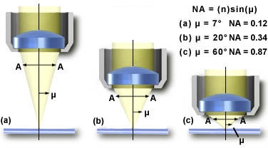
Numerical Aperture (N.A.), resolving two adjacent points, Airy discs
Physics tells us that the maximum magnification obtained through a light microscope is 400x: the closest two distinct points can be and still be resolved is 0.2 micrometer. This limitation is the result of light being diffracted by the object under observation and because diffracted light interferes with the image.
The smallest distance between two points which can be resolved with an oil immersion objective of the highest quality (Numerical Aperture of 1.4) and white light was studied by Ernst Abbe in the 19th century. The resolving power (s) of the light microscope is empirically given by
s =
l /(2nsin i)where n is the refractive index of air (n = 1.0), water (n = 1.33) or immersion oil (ne23=1.5180), l is the wavelength of the light (530 nm for green light) and i is half the angle subtended by the objective front lens at the object plane. Usually nsin i is called the numerical aperture (NA) of the objective.
Another way of looking at the resolving power (R) of the microscope:
R = 1.2 * l / NAobj + NAcond
where 1.2 is a mathematical shape function (Bessel function, round aperture)
l (lambda) is the wavelength of light.
The most important message from this equation is that the NA of the condenser
should match the NA of the objective in order to obtain good results.
The numerical aperture (N.A.) is basically a value that describes the quality of a lens.
It is derived from the size of the lens, its working distance and
the index of refraction.
All objective lenses will state the numerical aperture on the side of the barrel.
A good rule of thumb is that the effective magnification of an
objective is its numerical aperture times 1000. So a 40 x objective that has a
N.A. of 0.65 has an effective magnification of 650 times.
If you magnify beyond this you will
only get empty magnification. Empty magnification increases the size,
but does not increase the detail, due to the limitation of the resolving
power of the optical system.
It can be seen from the formula that the resolving power improves with shorter wavelength. Ultra violet microscopes have higher resolving power, and the electron microscope higher still, but the latter suffers from the inconvenience that the electron beam requires a vacuum. In spite of these limitations, modern techniques have enabled the observation of objects smaller than the above theoretical considerations would allow.
Hints and tips
Take care to use white light and turn the intensity of the lamp you are
using as far as necessary to obtain this, it will improve the resolving
power of the microscope. If the intensity of the light is too high for
comfortable viewing, do not turn down the lamp but use neutral density filters
to lower the light intensity. For anoverview of neutral density filters, see table below.
Using red light decreases the resolving power of the microscope, as can
easy be calculated with the above mentioned formula.
| Neutral-density filters and transmitted light | |
| Filter | Percent transmitted light |
| .1 | 80 |
| .2 | 63 |
| .3 | 50 |
| .4 | 40 |
| .5 | 32 |
| .6 | 25 |
| .9 | 13 |
| 1.0 | 10 |
Magnification to the eye is determined by multiplying the objective times
any intermediate magnification factor times the eyepiece.
Many microscopes have additional magnification factors associated with accessories like
fluorescence attachments or dual viewing systems.
Example: (Objective 40X)x(Fluorescence Attachment 1.25X)x(Eyepiece 10X) TOTAL:500X
The eyepiece has a second value besides magnification, the field of view (FOV)
number.
Divide the field of view number by the magnification of the objective plus any
intermediate factor. FOV = Field number/MT where MT=MobjxMproj
Example: 10x objective, 1x projection lens and 18 mm field number
FOV = 1.8 mm = 18/(10 x 1)
Special Note:
The eyepiece magnification has no effect on the field of view. An 8x/20FOV eyepiece has
the same field diameter as a 10X/20FOV eyepiece
Depth of field (DOFi) is the area in front of and behind the specimen that will be in
acceptable focus. The depth of field deals with the focus plane of the specimen.
The depth of field is related to the wavelength (lambda) of the light and to the angle
of acceptance of the lens, which is dependent on the focal length, which in turn
determines the numerical aperture (N.A.). In additon the refractive index, if different from
1.0 (air) must be multiplied with the wavelength (lambda).
Depth of field: 
The practical depth of field is much better than what the equation would predict. This is because the microscope manufacturer has stop down the iris diaphragm to get superior results. At the low magnification the difference between the practical and the theoretical is much greater. This is a function as to how small and round the iris diaphragm can be made.
| DOFi related to NA (green light) | ||||||
| NA | 0.25 | 0.30 | 0.50 | 0.65 | 0.85 | 0.95 |
| DOF (um) | 8.52 | 5.83 | 1.91 | 0.99 | 0.40 | 0.19 |
The range of acceptable focus for the image is called depth of focus.
The criterium for acceptable focus is ultimately dependent on the circle of minimum
confusion, the summation of all the optical aberrations.
Depth of focus is essential the same as depth of field but for one important difference,
that being magnification (M). With higher magnification depth of field becomes
shorter, however higher magnification increase the depth of focus for the image.
This is because the magnification is done with a projection lens. R.P means Resolving
Power, N.A. is the Numerical Aperture.
Depth of focus: ![]()
For optimum results in light microscopy, precise control of the light path should start before the light reaches the specimen.
Koehler illumination provides the most even illumination in the image plane and allows for
effective contrast control. Koehler illumination is critical when performing
techniques like Phase or DIC and also helps eliminate the likelihood of dust particles
from being imaged in the object plane.
Setting up Koehler illumination is also critical for digital image analysis, as
the quality of the image data relates directly to the quality of the data obtained
from measuring image features!
Dr. August Koehler published a paper in 1893 that described a method to
obtain the highest intensity of even illumination from a nonhomogeneous source.
Applying the "Koehler" method requires the control of 2
iris diaphragms in the light path: the Field and the Aperture diaphragm. The Field
eliminates all stray light by restricting illumination to the actual area under
observation. The aperture (condenser diaphragm) controls the cone of light
transilluminating the sample so it fills the aperture of
the microscope objective, thus optimizing depth of focus and image contrast.
The relationship of diaphragm position and objective lens magnification can
be seen above.
In the transmitted light system, the light is directed to a substage
condenser lens with a numerical aperture that approximates the highest
numerical aperture of the objective lenses.
The substage condensor is lowered to expand the illumination field when
low numerical aperture objective lenses are in use.
Maximum theoretical resolution is the point where the condenser numerical aperture
matches the objective numerical aperture. When using apochromat lenses, use the
full N.A. If you are using standard achromat objectives multiply the N.A. by 0.7,
that will be your best practical resolution.
Adjusting the iris diaphragm does this. Some iris diaphragms have calibrated
markings to indicate what the condenser numerical aperture is. In which case you
simple turn the lever to the objective N.A. value. If your microscope is not so
equipped then you will need to remove the eyepiece and look down the tube of the
microscope. What you will see is the back of the objective lens. There will be no
image visible just an illuminated disc.
If necessary a telescope can be place into to eyepiece tube to view the objective
better. Adjust the iris diaphragm so that the leaves of the aperture match the edge
of the lens. This is the point of maximum resolution.
If you open the iris diaphragm any further you will just increase flare. If you
stop down the iris diaphragm you will trade off resolution for contrast and depth of
field. It is up to you to determine the amount of contrast needed for you specimen.
In general, however set the diaphragm to maximum resolution.
It is up to the observer to determine how much resolution to trade off for contrast and depth of field. This requires an understanding of the specimen and what you want to see. For example, if you are viewing stained bacteria that are fixed to a glass slide. You will not need much depth of field. So you can set the microscope to its maximum resolution. If the specimen was not well stained, when you could trade off some of the resolution for contrast.
The microscope must have a vertically adjustable, centerable condenser and iris diaphragm.
Before you start make sure the lamp bulb is centered.
Hints and tips
If you wear corrective lenses take them off for microscopy.
The microscope itself is your lens! If you have astigmatism, the microscope cannot
correct your vision.
Note that the specimen may appear " washed out," that is, there is little detail,
when the aperture diaphragm (in the condenser) is completely open. Note also that the image
becomes dark and distorted when the aperture diaphragm is completely closed. Achieve
optimum contrast by adjusting the aperture so that you can see detail, but not so much
that the edges of objects are distorted.
Centering, field iris and aperture iris adjustments will change with each objective
with a transmitted light microscope.
As the magnification and NA of the objective increases, the field diaphragm setting
becomes smaller and the aperture diaphragm setting gets larger. Do not forget
to adjust the light, field and aperture diaphragm when you
change the objective lens!
When a microscope is properly setup for Koehler illumination, the ray paths for
illuminating light produce a focused image of the lamp filament at the plane of
the substage condenser aperture diaphragm, the back focal plane of the objective,
and the eyepoint (also called the Ramsden disk) of the eyepiece.
These areas that are in common focus are often referred to as conjugate planes,
which are critical in achieving proper Koehler illumination. By definition, an object
that is in focus at one plane is also in focus at the other conjugate planes of that
light path. In each light pathway (both image-forming and illumination), there are
four separate planes that together make up the conjugate plane set.
Conjugate planes in the path of the illuminating light rays in Koehler illumination include:
Likewise, the conjugate planes in the image-forming light path in Koehler illumination include:
Hints and tips
Conjugate focal planes are often useful in troubleshooting a microscope for contaminating
dust, fibers, and imperfections in the optical elements.
If these artifacts are in sharp
focus, it follows that they must reside on or near a surface that is part of the
imaging-forming set of conjugate planes. Members of this set include the glass
element at the microscope light port, the specimen, the reticule in the eyepiece,
and the bottom lens element of the eyepiece.
Alternatively, if these contaminants are fuzzy
and out of focus, look for them near the illuminating set of elements that share
conjugate planes. Suspects in this category are the condenser top lens (where dust
and dirt often accumulate), the exposed eyepiece lens element, and the objective
front lens.
A condenser controls the angle of light (expressed as "numerical aperture"
or "NA.") hitting the specimen. Adjusting this angle is an important part
of setting Koehler illumination to optimize both resolution and contrast.
For best resolution, the angle should match the collecting
angle of the objective (NA condenser = NA objective). To improve
contrast however, the iris located below or within the condenser
needs to be closed by about 25%. For a 1.25 NA/oil immersion condenser, this
reduces the working aperture to about 0.9. So why not use a less expensive,
less messy 0.9 NA/dry condenser to begin with?
Lenses do not focus light perfectly. Chromatic and spherical aberations occur on-axis and coma and astigmitism occur off-axis.
Chromatic aberration occurs due to the variation of refractive index with wavelength for a lens material (there is no chromatic aberation in curved mirrors). This wavelength dependence results in slightly different focal lengths for different wavelengths of light. Compound lenses, called achromats, can reduce or eliminate chromatic aberation because the components are chosen such that the variation in refractive index as a function of wavelength cancels out.
Spherical aberation results because the actual focal point of a light ray depends on its distance from the optic axis. Plan lenses can reduce or eliminate spherical aberration.
Coma is caused by the distortion of a wavefront as it encounters an optic asymmetrically. The result for collimated incoming light is a circle instead of a point image. The light rays farther from the optic axis have more severe aberration and the resulting image looks like a comet-shaped series of circles.
The projection of an optic off-axis looks squashed in one direction. The squashed direction focuses light to a greater extent than the normal dimension. The result is two line images.
Hints and tips
As most lens systems are designed to work best with green light, a simple way to reduce
chromatic aberration is to use a broad band interference filter,
which only lets green light (around 530 nm) pass through.
It is a good practice to use a green filter whenever you
do not need color information.
There are ways to create contrast in microscopy samples without the need to stain tha sample, a short overview is given below.
Phase contrast microscopy detects differences in phase due to a difference in
refractive thickness or thickness of the unstained sample.
You need a special objective with a phase ring.
DIC detects phase gradients in unstained samples. It works by means of
polarizers and modified Wollaston prisms (Nomarsky prisms).
You need a special setup with Nomarsky prisms and a low-strain objective.
It started in 1983 at Janssen Pharmaceutica in Beerse, Belgium, with the Quantimet 970 Image Analyzer made by Cambridge Instruments. The team at Janssen developed Nanovid microscopy in 1985. The original Janssen automated imaging system, of which the first system was built in 1993, was based on Carl Zeiss microscopes, equipped with high-precision Märzhäuser Wetzlar scanning stages and various CCD camera types. Software development was based on the SCIL Image system, running on SGI IRIX systems and developed in ANSI C. I joined the team at the Life Science department at Janssen on 31 Dec. 1996, working on image analysis applications with Frans Cornelissen and Jan-Mark Geusebroek. A patented proprietary objectbased auto-focusing system, scalespace and spatial color model algorithms, allowed for unprecedented performance. In 2001, I continued my work at MAIA SCIENTIFIC (Geel, Belgium), a subsidiary of Harvard Bioscience, while system development at Janssen was discontinued. The system became known as the MIAS-2™ system, equipped with Hudson Robotics and the Linux-based eaZYX software system. In 2005, I left MAIA SCIENTIFIC and later on the company became a subsidiary of Digilabs.
I am indebted, for their pioneering work on automated digital microscopy and High Content Screening (HCS) (1988-2001), to my former colleagues at Janssen Pharmaceutica (1997-2001 CE), such as Frans Cornelissen, Hugo Geerts, Jan-Mark Geusebroek and Roger Nuyens, Rony Nuydens, Luk Ver Donck, Johan Geysen and their colleagues.
Many thanks also to the pioneers of Nanovid microscopy at Janssen Pharmaceutica, Marc De Brabander, Jan De Mey, Hugo Geerts, Marc Moeremans, Rony Nuydens and their colleagues. I also want to thank all those scientists who have helped me with general information and articles.
The author of this webpage is Peter Van Osta.
Private email: pvosta at gmail dot com